Ford 6.0L Power Stroke Diesel Engine 2004-2006 Service Repair Manual
|
Ford 6.0L Power Stroke Diesel
Compatible with: All Windows Systems |
Ford 6.0L Power Stroke
Just £9.95
Instant Download |
Please read before buying. This is an engine manual. It is not a full truck workshop manual, and there are no brake, suspension, steering, body, transmission or vehicle wiring sections in it. The main book is also International's document, not Ford's, so it calls the engine the VT 365 and the words “Ford” and “Power Stroke” do not appear in it. That is not the wrong manual. International built this engine for Ford and the VT 365 and the 6.0L Power Stroke are the same thing. A Ford-badged engine section is included alongside it so you have both sets of terminology.
The engine Ford sold as the 6.0L Power Stroke was designed and built by International Truck and Engine Corporation, who called it the VT 365. Ford never published International's engineering manual for it, and the Ford workshop manual covers the engine as one section among a hundred. This download is the other way round: 963 pages, almost all of it engine.
Three documents are included. The main one is International's own factory service manual, document number EGES-295-2, dated to the 2004 to 2006 model years and running to 412 pages. With it comes Ford's own engine section 303-01C from the 2006 F-250 to F-550 workshop manual, 239 pages, and the 2006 owner handbook for the truck, 312 pages.
Which vehicles this manual fits
- Fits: the 6.0L Power Stroke diesel V8 as fitted to the Ford F-250, F-350, F-450 and F-550 Super Duty and to the Ford Excursion. The same engine is the International VT 365 in International and IC Bus chassis, and this is the manual for it under either name
- Covers years: 2006, 2005, 2004
- Earlier and later trucks: the 6.0L was fitted from 2003 to 2007 in the Super Duty and from 2003 to 2005 in the Excursion. EGES-295-2 is the 2004 to 2006 revision, so the mechanical work, the measurements and the torque figures apply across the run. Emissions calibration is the part that moved, and the manual itself carries separate emission label pages for 2004 and 2005 and for 2006, so check any emissions figure against your own vehicle
- Engine: 365 cu in (6.0L), 4 OHV/1 cam-in-crankcase V8, bore and stroke 95 mm by 105 mm, compression ratio 18.0:1, VGT turbocharged with charge air cooling, Digital Direct Injection. Base rating 175 bhp at 2600 rpm and 460 lbf•ft at 1400 rpm, with the other ratings listed in Appendix A
- Firing order: 1-2-7-3-4-5-6-8, with the right bank numbered 1, 3, 5, 7 viewed from the flywheel end
- Language: English
- Pages: 963 across six PDFs in one download
- File type: PDF (supplied as a ZIP containing three foldered documents)
Inside this manual
Every entry below is a heading taken from the documents themselves. The chapter titles in capitals are International's; the numbered section is Ford's.
- Service Diagnosis
- Safety Information
- ENGINE SYSTEMS
- Engine Identification, Serial Number and Emission Labels
- Engine Description
- Engine Component Locations
- Air Management System (AMS)
- Charge Air Cooler (CAC)
- Variable Geometry Turbocharger (VGT)
- Exhaust Gas Recirculation (EGR) System
- Fuel Injection, Fuel Management and Injection Control Pressure (ICP) Systems
- Fuel Injectors
- Fuel Supply System and Fuel Flow
- Lubrication System
- Cooling System
- Electronic Control System Components and Injection Drive Module (IDM)
- Engine and Vehicle Sensors
- Glow Plug Control System
- MOUNTING ENGINE ON STAND
- ELECTRONICALLY CONTROLLED VARIABLE GEOMETRY TURBOCHARGER (VGT)
- VGT Control Valve Removal and Installation
- Axial End Play, Free Rotation and Housing Rub Checks
- MANIFOLDS AND EXHAUST GAS RECIRCULATION (EGR)
- Intake Manifold and EGR Cooler
- Exhaust Gas Recirculation (EGR) Valve
- Exhaust Gas Recirculation (EGR) Cooler
- Left and Right Exhaust Manifolds, Tubing and Warp Test
- CYLINDER HEAD AND VALVE TRAIN
- Valve Covers, ICP Sensor and Rear Heat Shield
- High-pressure Oil Rail Assembly
- Rocker Arm Carrier
- Valve Bridges and Pushrods
- Hydraulic Cam Followers
- Removing Valves from Cylinder Head
- Fuel Injector and Glow Plug Sleeve Removal
- Cylinder Head Inspection, Valves Installed and Removed
- Tightening Sequence for Cylinder Head Bolts, M14 x 193 and M8 x 70
- Cylinder Head Applications
- Fuel Injector Assembly
- FRONT COVER, VIBRATION DAMPER, and GEROTOR OIL PUMP
- Front Oil Seal and Wear Sleeve
- Water Pump and Thermostat
- OIL PAN, UPPER OIL PAN, and OIL PICKUP TUBE
- POWER CYLINDERS
- Connecting Rod and Piston Assembly
- Piston Disassembly and Ring Assembly
- Connecting Rod Bore Out-of-round, Taper and Bearing Fit Checks
- Piston Pin Inspection
- CRANKCASE, CRANKSHAFT and BEARINGS, CAMSHAFT and BUSHINGS
- Lower Crankcase
- Camshaft Bushings and Measuring Camshaft Bushings
- Piston Cooling Tubes
- Cylinder Deglazing
- Crankshaft and Timing
- CMP and CKP Sensors, Coolant Heater and Heating Element
- OIL COOLER and FILTER HOUSING
- Oil Cooler Cover and Filter Housing Assembly
- Oil Cooler Disassembly and Coolant-Side Leaks
- Pump Inlet Strainer
- ENGINE ELECTRICAL
- Description of Engine Sensors and Valves
- Injection Pressure Regulator (IPR) Valve
- Exhaust Back Pressure (EBP) Sensor
- ECM, IDM and Mounting Bracket
- Main Engine Wiring Harness
- Glow Plug Harness, Bracket and Relay
- HIGH-PRESSURE OIL PUMP
- High-pressure Flow Schematic
- High-pressure Oil Pump Assembly
- Branch Tube Assembly, Adapter and Snap To Connect (STC) fitting
- FUEL SYSTEM
- Fuel Prescreen Element, Filter Assembly and Tubing
- Priming the Fuel System
- REAR COVER, FLYWHEEL, and POWER STEERING GEAR DRIVE
- Flywheel and Flexplate Surface Runout
- Rear Main Seal and Wear Sleeve
- Power Steering and Fuel Pump Assembly
- IN-CHASSIS PROCEDURES
- Appendix A Specifications
- Appendix B Torques
- Appendix C Special Service Tools
- Ford section 303-01C Engine 6.0L Diesel
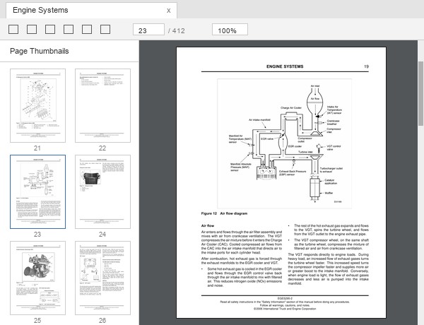
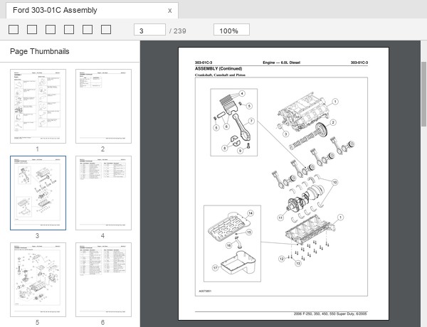
Sample pages from this manual
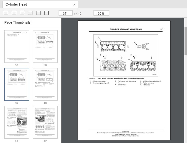
These are real pages taken from the files, so you can see exactly what you are buying:
What you can repair with it
The cylinder heads are the largest single chapter, running from page 99 to page 156. It takes the valve covers off, lifts the high-pressure oil rail, strips the rocker arm carrier, pulls the heads, removes the valves, and then goes through fuel injector sleeve and glow plug sleeve removal and replacement. Reassembly gives the bolt sizes by name, M14 x 193 and M8 x 70, and a tightening sequence for the head bolts. Cylinder head applications are listed separately because the heads changed during the run.
The parts of this engine that people actually chase are all in here as procedures. The EGR cooler and the EGR valve have their own removal, cleaning and installation entries. The oil cooler has a disassembly procedure and a dedicated heading for coolant-side leaks. The high-pressure oil pump gets its own chapter with a flow schematic, the branch tube assembly and the Snap To Connect fitting. The turbocharger chapter covers removal down to the control valve, and includes the axial end play check and the free rotation and housing rub check, which is how you decide whether the unit is finished.
Below the heads it is a full overhaul book. Pistons and connecting rods come with the bore out-of-round and taper check, the bearing fit check and the piston pin inspection. The crankcase chapter covers cylinder deglazing, camshaft bushing measurement and the crankshaft timing. Appendix A holds the specifications, Appendix B the torques including a standard torque table and the special torques by assembly, and Appendix C every special service tool with its ZTSE number.
Ford's section 303-01C runs alongside all of that with Ford part numbers and Ford tool numbers such as 303-770 for the crankshaft rear seal installer and 303-1112 for the injection pressure regulator socket, so you can work from whichever numbering your supplier or your scan tool is using.
Manual language and format
English throughout. The download is a ZIP holding three folders. Folder 01 is International's service manual in four PDFs, split at the chapter boundaries but numbered continuously, so page 250 sits in Part 3 exactly where the contents page says it does. Folder 02 is Ford's section 303-01C as a single PDF. Folder 03 is the 2006 owner handbook. A read-me file at the top of the archive explains what each folder is before you open anything.
Every file is a normal PDF with searchable text, so you can look up a part name or a torque figure across a whole part in one go. Nothing needs installing and there is no activation.
Questions about this manual
Is the VT 365 the same as the 6.0 Power Stroke?
Yes. International Truck and Engine Corporation designed and built the engine and called it the VT 365. Ford bought it, badged it Power Stroke and quoted the displacement in litres. 365 cubic inches is 6.0 litres. The specification table on page 9 of the service manual lists it as “365 cu. in (6.0L)”, which is the two names sitting in the same line.
Who makes the VT 365 engine?
International Truck and Engine Corporation, whose copyright line appears at the foot of every page of the service manual. The same company later became Navistar. Ford assembled the trucks but did not build this engine.
Why does the manual never say Ford or Power Stroke?
Because it is International's internal document, written for their own technicians and their own chassis. It is the more detailed of the two books for exactly that reason. Ford's own engine section is included in Folder 02 for anyone who needs the Ford wording and Ford part numbers.
Does it cover the problems this engine is known for?
It covers the work, not the reputation. A service manual will not tell you which years to avoid, and we are not going to pretend otherwise. What it does have is the procedure for every component that commonly comes off one of these engines: EGR cooler, EGR valve, oil cooler including the coolant-side leak check, cylinder heads with the bolt tightening sequence, fuel injectors and their sleeves, the high-pressure oil pump and the STC fitting, glow plugs and the glow plug relay, and the turbocharger with its condemnation checks.
Does it include wiring diagrams for the truck?
No. The Engine Electrical chapter covers the engine's own harness, the ECM and IDM mounting, the glow plug harness and every engine sensor by name, but there are no vehicle wiring diagrams. Those are in our Ford Super Duty workshop manuals, which cover the truck by model year.
I have a 2007 truck. Will this help?
For mechanical work, yes. EGES-295-2 is the 2004 to 2006 revision and the engine's mechanical build did not change after it. Treat the emissions material with care and check any calibration figure against your own vehicle, because that is the part that moved year to year.
Do I need the truck workshop manual as well?
If the job is inside the engine, no. If the job involves anything bolted to the truck rather than the engine, then yes, because none of that is here. The 2006 owner handbook in Folder 03 covers the everyday side, warning lights, capacities and maintenance intervals, but it is not a repair book either.
How you receive it
Secure checkout, with the download link issued the moment payment clears. Nothing is posted. The files are yours to keep and can be downloaded again while the link stays active.